SDDC Architecture – Core and POD design
Notice: This article is more than 9 years old. It might be outdated.
This article is part of a series of articles, focusing on the architecture of an SDDC as well as some of its design elements. In this post we want to look at the physical layer of our SDDC architecture (See Figure 1).

Requirements
A Software Defined Data Center promises to be the new underpinning or platform for delivering today’s and tomorrow’s IT services. As such this next generation infrastructure needs to address some shortcomings of today’s infrastructure in order to be successful:
- Highly automated operation at Scale: Leaner organization that scales sub-linearly with an operating model build around automation. Leverage modular web-scale designs for unhampered scalability.
- Hardware and Software efficiencies: Support on-demand scaling for varying capacity needs. Improved resource pooling to drive increased utilization of resources and reduce cost.
- New and old business needs: Support legacy applications with traditional business continuity and disaster recovery, besides new cloud-native applications.
Physical Layer Design Artifacts
Within the Physical Layer we want to look at these design artifacts:
- POD and Core Design: POD (Point-of-Delivery) as an atomic building block of Data Center resources, connected to a CLOS network for increased scale, agility, flexibility and resilience.
POD and Core Design
More and more enterprises are looking at this concept known from web-scale companies in order to streamline functions and cost, but especially to support future growth. For this they leverage a design concept called “POD and core”, where data centers are build out with small chunks of equipment dedicated to different types of workloads and different capabilities. This approach, which we will here discuss further is very well suited for deployments that start small, but then grow to large-scale over time, while sticking to the same overall architecture. As a SDDC is a journey with multiple implementation phases to address maturing requirements, capabilities and demand, this approach is very suited here and therefore growing in popularity.
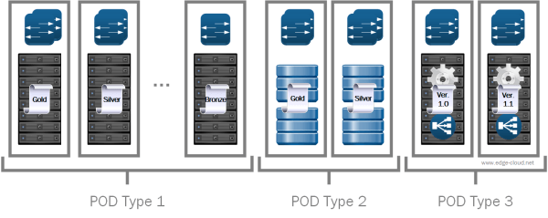
With the POD and Core design, data center architects design a small collection of common building blocks to suit various application needs. These building blocks can include different combinations of servers, storage, network equipment, etc. and can each be designed with varying levels of hardware redundancy and quality of components to fulfill the needs of the specific requirements. Over time individual building blocks can evolve through new revisions, allowing to address lessons-learned without the need to rip-and-replace existing hardware (See Figure 2).
Moreover by breaking down the entirety of a data center into groups of PODs, you are applying a divide and conquer methodology, making it easier for architects to understand how their gear fits together as a whole and allowing them to focus on optimizing individual pieces.

The common building blocks are then connected to a network core, that distributes data between them. This kind of network core has to address different requirements than traditional data center networks. Traffic patterns are transforming more and more from client-server (North-South) to between servers (East-West). Scale increases and has to connect 10s of thousands to 100s of thousand endpoints. Agility should improve by allowing to add PODs within hours, not weeks or month and new logical networks should be spun up in seconds and not weeks. At the same time the POD design calls for a high flexibility of the network design by (re-)using the same infrastructure for very different building blocks. All this should happen while improving the resilience through fine grained failure domains.
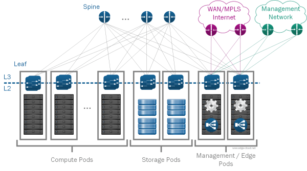
A very elegant answer to these physical network requirements is a L3 based CLOS network, also called Spine/Leaf (See Figure 3).

One of the guiding principle for such deployments is that the network virtualization solution via Overlay Networks allows to do away with any spanning of VLANs beyond a single POD. Although this appears to be a simple change, it has widespread impact on how a physical network infrastructure can be built and on how it scales. We can now use proven L3 capability - e.g. via Internet-scale proven BGP - between PODs, while restricting the L2 domain to the POD itself. This greatly reduces the size of the failure domain.
POD types
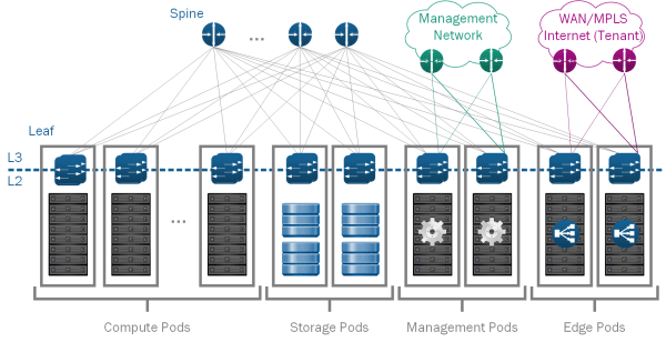
For the SDDC we will use four kinds of pods (See Figure 4):

- Compute: Compute PODs make up the main part of the infrastructure where virtual machines for end-user workloads are hosted. Different types of compute PODs with varying levels or redundancy, built-quality and price can be mixed within a single SDDC. This approach provides separate compute pools for different types of SLAs. While it is possible for Compute PODs to include local storage - e.g. via vSAN, doing so creates silos as the usage of this storage is limited to within the POD. If using separate storage PODs, storage from these PODs can be used by multiple compute PODs and one compute POD can use storage from multiple Storage PODs. This increases flexibility, as it allows you to grow storage and compute independently.
- Storage: Storage PODs provide network accessible storage via NFS or iSCSI. Similar to the other pods, different levels of SLA can be provided via different kind of storage pods, ranging from JBODs with SATA drives and with minimal to no redundancy to fully redundant enterprise class storage arrays, filled with SSDs.
- Management: The Management Pod runs all virtual machines instances that are necessary to operate the management functionality of the SDDC. More specifically this includes all VMware management components, including vCenter Server, NSX Manager, Cloud Management Platforms (CMP) - such as vCloud Director, VMware vRealize Automation or VMware Integrated OpenStack - and other shared management components. This POD also provides external network connectivity to the Management network and as such does not include any tenant specific IPv4 or IPv6 addressing.
-
Edge: The SDDC spine-leaf network fabric itself does not provide external connectivity. Instead external connectivity is pooled into so-called Edge PODs in order to reduce cost and better scale changing demand for external connectivity. The Edge pods connect to the data center fabric as well as the Internet or Enterprise-internal Wide Area Networks (WANs). They therefore also provide the on-/offramp functionality between the overlay networks of the network virtualization solution and the external networks. This is accomplished by running VM-based edge services on general compute hardware. As such the main functions provided by an edge rack are:
- Provide on-ramp and off-ramp connectivity to physical networks
- Connect with VLANs in the physical world
- Optionally host centralized physical services
Tenant-specific IPv4 and IPv6 addressing is exposed to the physical infrastructure in the edge rack. This is either done via L3 connectivity, using static or dynamic routing or via L2 connectivity, bridging VLANs from the Internet / WAN side into VXLANs on the SDDC network fabric side.</li> </ul>
In small to medium sized deployments it is recommended to combine Management and Edge POD into a single rack as compute requirements for these two types of PODs are rather limited. Also these POD types both require external network access, making them a prime candidate for combining.
In large deployment it is advisable to split Management and Edge POD. This allows to scale external connectivity of the SDDC by adding additional Edge PODs (See Figure 5).

PODs and Service Levels
As already mentioned it is possible to have different pods of the same type, providing different characteristics for varying requirements. As such one compute pod could e.g. be architected using full hardware redundancy for every single component (redundant power supplies through ECC memory chips) for increased availability, while at the same time, another compute pod in the same SDDC could use low-cost hardware without any hardware redundancy. With these kind of possible variations an architect is better suited to cater to the different requirements for the SDDC to cater to new and old business needs.
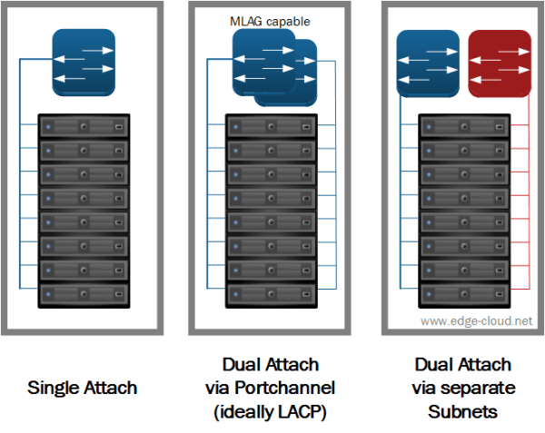
From a network perspective you also have multiple options for attaching servers to the Leaf network node (See Figure 6). Which option you choose depends on your requirements - including cost and available / approved hardware.

The options in detail are:
- Single Attach: Servers are connected via a single (usually 10 GigE) network connection to a single leaf switch. This attach option provides no network redundancy. But it is nevertheless frequently used by webscale companies, where failures of servers or entire PODs are easily mitigated by the infrastructure or application software layer.
- Dual Attach via Port-channel: In this case the server is connected via two (usually 10 GigE) network connections to a pair of switches. These switches must support Multi-Chassis Link Aggregation Group (MLAG) capabilities to provide a port-channel (ideally via LACP) towards the servers. Various vendors offer data center switches that support this capability, e.g. by allowing to stack the Top-of-Rack (ToR) switches.
- Dual Attach via separate subnets: The other option for Dual attaching servers is to use multi-homing. Here each server is also connected via two (usually 10 GigE) network connections to two upstream switches. But in this case, the upstream leaf switches are truly separate and each offer a separate subnet towards the server. As a result the server would e.g. have two separate subnet for management capabilities available.
Summary
This article highlighted the concept of the POD and Core design. It especially outlined how this concept fulfills our SDDC requirements:
- Highly automated operation at Scale: The modularity of the POD design allows to quickly and easily scale up and down the SDDC based on actual demand. Due to the high uniformity of a POD it is possible to automizing parts of adding and removing a POD, while reducing physical labor to standard procedures.
- Hardware and Software efficiencies: The modular PODs not only allow on-demand scaling for varying capacity needs, but especially promote resource pooling to drive increased utilization of resources and reduce cost. This is especially achieved by splitting compute and storage capacity in separate resources and thereby allowing independent pooling and scaling.
- New and old business needs: Using different instance types for the various, it is possible to offer differentiated SLAs through varying levels of hardware cost. As a result it is possible to remove redundancy from hardware, thereby reducing cost, while allowing infrastructure or especially application software layers to mitigate this missing feature. As a single SDDC can include pods of varying SLA type, this allows the operation of legacy applications with traditional business continuity and disaster recovery needs right along new cloud-native applications.
