SDDC Architecture - Virtual PODs for Management applications
Notice: This article is more than 9 years old. It might be outdated.
This article is part of a series of articles, focusing on the architecture of an SDDC via VMware Validated Designs.
Requirements
A Software Defined Data Center promises to be the new underpinning or platform for delivering today’s and tomorrow’s IT services. As such this next generation infrastructure needs to address some shortcomings of today’s infrastructure in order to be successful:
- Highly automated operation at Scale: Leaner organization that scales sub-linearly with an operating model build around automation. Leverage modular web-scale designs for unhampered scalability.
- Hardware and Software efficiencies: Support on-demand scaling for varying capacity needs. Improved resource pooling to drive increased utilization of resources and reduce cost.
- New and old business needs: Support legacy applications with traditional business continuity and disaster recovery, besides new cloud-native applications.
The motivation
The concept of the Management Stack Virtual POD can be considered as part of the secret sauce for the VMware Validated Designs. This is a concept only found in the management stack and aims at providing SDDC management application with low integration efforts, while treating them as sub-systems and providing advanced security.
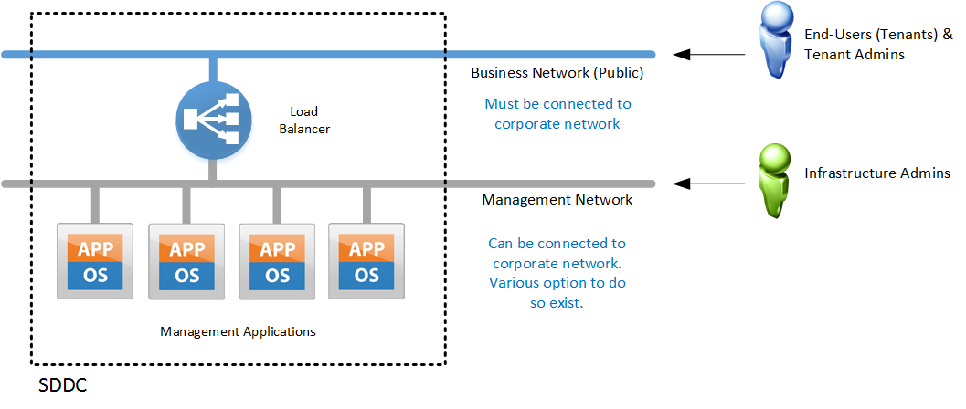
One of the main ideas behind this concept is depicted in Figure 1:

The SDDC based on a VMware Validated Design use two main network segments:
- Business Network: This network must be connected to the corporate network of the organization where the SDDC is being deployed. Otherwise end-users and tenant admins of the SDDC have no ability to access components such as VMware vRealize Automation. As a result the SDDC would not be able to deliver any business value.
-
Management Network: Only infrastructure-admins should have access to this network. In fact end-users and tenant-admins should not have access to this network at all. The VMWare Validated Design supports various options for connecting to this network, where the best choice depends on the use cases for the SDDC within the organization where it is deployed:
- Directly connect to the corporate network via static or dynamic routing with a firewall in between
- Connect via MPLS from off-site for a managed services offering. Turns out that a VMware Integration Partner, delivering VMware SDDC today, follows exactly this path.
- Provide a Jump-Host for more secure access from the corporate network
- Many other ways to connect admins to admin network
SDDC management workloads are placed on the management network and fronted with a load balancer. This is a typical concept for web application and shouldn’t be new or surprising. With VMware products this concept already used widely by VMware Integrated OpenStack (VIO), but also VMware vCloud Director and VMware vRealize Automation. </li> </ul>
The container concept
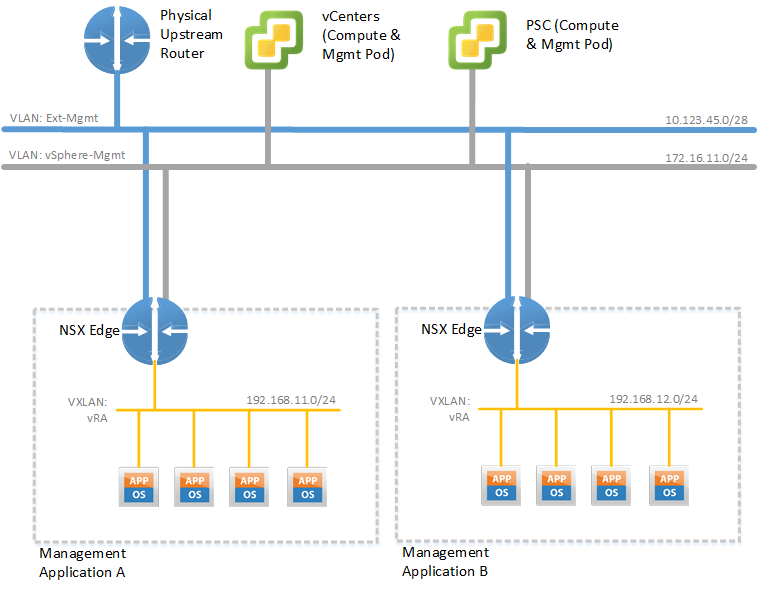
The above concept depicted in Figure 1 can only be considered as an interim step. We will certainly keep the concept of the business network vs. the management network. But in addition we place each management application in a dedicated Virtual POD with an VMware NSX Edge acting as router, firewall, and load balancer at the boundary of this container. As such we end up with one container for VMware vRealize Automation, another one for VMware vRealize Operations and the third one for VMware vRealize LogInsight (See Figure 2).

This approach provides the following benefits:
- Security: Granular yet simple control who can access what services within a Virtual POD.
- Modularity: Replace or upgrade an application without breaking the entire SDDC as dependencies go via well-know interfaces.
- Simplicity: Reduces the number of required IP addresses on the corporate network, but also keeps the integration effort low, by not requiring dynamic routing towards the corporate network.
- Business Continuity / Disaster Recovery (BC/DR): Simplifies the Business Continuity / Disaster Recovery (BC/DR) story with VMware Site Recovery Manager (SRM). See below for more.
- IPv6: Ability to provide the management applications over IPv6 by solely enabling IPv6 on the Virtual IP (VIP) of the NSX Edge load balancer.
Virtual PODs for cross-region failover via SRM
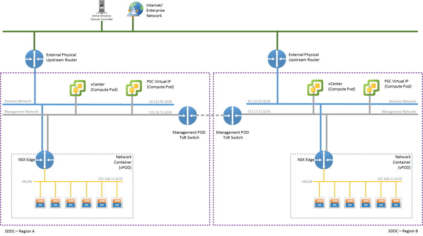
Let’s have another look at the Virtual POD concept and see how it performs within a multi-region setup, using VMware Site Recovery Manager (SRM) for Business Continuity / Disaster Recovery (BC/DR) purposes (See Figure 3). The key benefit of this approach is the ability to use a purely DNS-based service failover mechanism, instead of having to re-announce IPv4 routes from the recovery location.

One of the fundamental concepts of the Virtual PODs is that for a given management application, the same IPv4 subnet is used within each region’s VPOD. In the example, depicted in Figure 3 this means that the Virtual POD in bother regions uses the IPv4 subnet 192.168.11.0/24.
As a result, in combination with VMware SRM, there is no need to change the IP addresses and therefore also SSL certificates of the service nodes for a recovered application like VMware vRealize Automation. This is a major benefit as an application like VMware vRealize Automation requires multiple cumbersome steps - including manipulation of the database entries - to change the IP addresses of a once installed instance.
The NSX Edge devices in both regions have equivalent settings for load balancer rules and firewall rules, except for the IP addresses on the Business and Management network. As a result the virtual IPs (VIP) between these two different load balancers are obviously different, but the underlying load balancer configuration is the same.
The external facing service, while the Management application resides in Region A, is reachable under the VIP of that regions NSX Edge device. After a failover via SRM of the Management Application to Region B, the service is alive under that regions NSX Edge device.
Therefore in order to make the failover complete for end-users of the service, a change to the DNS name of the service is necessary. With that change the DNS entry is re-pointed from the VIP on the NSX Edge in Region A to the VIP on the NSX Edge in Region B.
Performing such a DNS update can be easily done using corresponding Dynamic DNS services on the Internet, building your own equivalent or using a simple script to update you Microsoft DNS server.
Again, no dynamic routing updates are necessary after a SRM failover towards the business network. In fact, you don’t even need to run dynamic routing towards the business network unless you want to.
Virtual PODs and SRM failover testing
An interesting, but also very important feature of VMware Site Recovery Manager (SRM) is the ability to test a failover. In this case the application remains operational and untouched in the primary location. In the recovery location a second instance of the application is created based on a snapshot of the most recent replicated data. While this failover-test application is running, replication between sites is unaffected. Also after the test completes the failover-test application along with the snapshot data can be discarded.
With the Virtual PODs you can test the functionality of the failover-test application in the actual environment that the application would be restored to. No special test network constructs are necessary. Instead you deploy the failover-test application into the second regions vPOD where you can access this application under the corresponding Virtual IP. You could even place a test DNS entry on this VIP. As long as you don’t touch the DNS entry for the primary application it will not be affected.
Summary
The Virtual POD network container is a very powerful, yet simple concept to provide the management applications of the SDDC with security, modularity, simplicity, improved BC/DR capabilities and IPv6 support. All this with a minimum of integration effort. I can therefore be seen as a major enabler for an SDDC based on the VMware Validated Design.
